
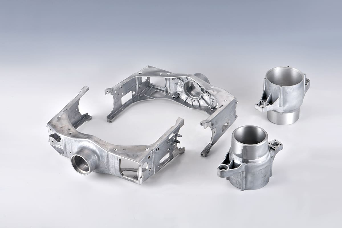
A change to an aluminum housing is inexpensive while it remains a CAD revision. The same change can become costly after a steel die has been cut, cooled, and tested. That difference makes early questions about alloy, wall geometry, ejection, and machined interfaces more consequential than a superficial review of the finished shape.
Projects involving die casting services benefit from treating tooling approval as a sequence of engineering decisions, each supported by a clear requirement or validation method.
Which Alloy Matches the Working Conditions?
The first question concerns service conditions, not the casting machine. A housing carrying electronics may prioritize heat transfer and low weight; a structural bracket may require a different balance of strength and ductility. The selected alloy influences casting behavior as well as the final part’s mechanical and thermal properties, so its designation should be stated before die design starts.
Available aluminum grades include A380/ADC12, A383, A356, A360, and AlSi10Mg. These designations are not interchangeable promises of identical performance. Wall thickness, casting method, subsequent machining, and any required finish all affect the practical choice.
If a part contacts another metal or operates outdoors, corrosion protection and surface treatment also belong in the initial specification. The answer may also determine whether exterior surfaces may carry parting lines or ejector marks. Such choices are easier to address during die-layout discussion than after the cavity has been machined.
Where Will the Melt Flow and Solidify?
Molten metal must fill the die cavity before it cools enough to obstruct flow, while the casting process must also control trapped gas, shrinkage, and thermal gradients. Long thin ribs, abrupt thickness transitions, and isolated heavy sections can complicate that task. Internal pockets that appear efficient in a solid model may be much harder to feed and solidify without defects.
Consistent wall sections, smooth transitions, and sensible rib junctions generally make filling and cooling easier to manage. Yet thinning every wall is not a complete solution: mounting bosses, threaded areas, and seals still need adequate material. The design review should consider where gates and runners can introduce metal, where overflow or venting may be needed, and which surfaces will later be removed by machining.
Can the Casting Be Released From the Tool?
A surface that looks accessible in an assembled product may be trapped inside the die’s opening direction. Draft on appropriate faces, accessible ejector locations, and carefully located parting lines are therefore part of functional design. Undercuts may require slides or other tooling actions, increasing mechanical complexity and the number of interfaces that must be maintained.
Core movement and ejection also influence surface appearance and dimensional variation. Hanstar Technologies uses cold-chamber processes for aluminum and magnesium, while its zinc casting operation uses hot-chamber equipment.
Its press range is 100–2,000 tons, with cast components up to 20 kg; these are equipment capabilities, not a guarantee that every cavity shape fits every press. A review of die casting services should establish the proposed machine, ejection strategy, and expected tool access before release.
Which Features Should Be Machined After Casting?
A near-net-shape casting still may not meet every assembly requirement directly from the die. Bearing seats, locating bores, tapped holes, and sealing interfaces can require CNC finishing. Assigning those operations early preserves suitable machining allowances and helps prevent a cast surface from being treated as an inspection datum when a machined feature is the true functional reference.
Hanstar Technologies coordinates die development, casting, CNC post-machining, inspection, and finishing. Its typical cast-dimensional tolerance is around ±0.1 mm, with ±0.05 mm possible for selected cast features and ±0.01 mm for suitable machined dimensions. The exact achievement depends on alloy, geometry, and the characteristics being measured. Those distinct limits should be reflected explicitly on the drawing rather than reduced to one blanket tolerance statement.
What Must Be Checked Before Production Tooling Is Accepted?
Tool approval is more credible when linked to first-article evidence. Initial castings can reveal misalignment, filling defects, machining-stock issues, or assembly interference while corrective changes are still being evaluated. Coordinate-measuring results for critical dimensions should be considered together with visual, functional, and fit checks appropriate to the component.
A sealed housing may additionally need a specified leak test, whereas a bracket might require checks of mounting position and material condition. Those test obligations should be defined in the project specification, not assumed for every casting order.
Planning also needs a realistic schedule. Hanstar’s indicative die-tooling period is generally four to six weeks, followed by an estimated two to four weeks of production depending on quantity and complexity. A schedule for die casting services should allow for design review, tool manufacture, trial castings, inspection, and any approved modifications; the first poured component is not automatically a production-qualified component.
The essential decision before tooling is whether the casting route can deliver both a manufacturable shape and verifiable assembly features. A tooling inquiry to Hanstar Technologies can identify the selected alloy, released model, and critical machined interfaces before those decisions are fixed in steel.